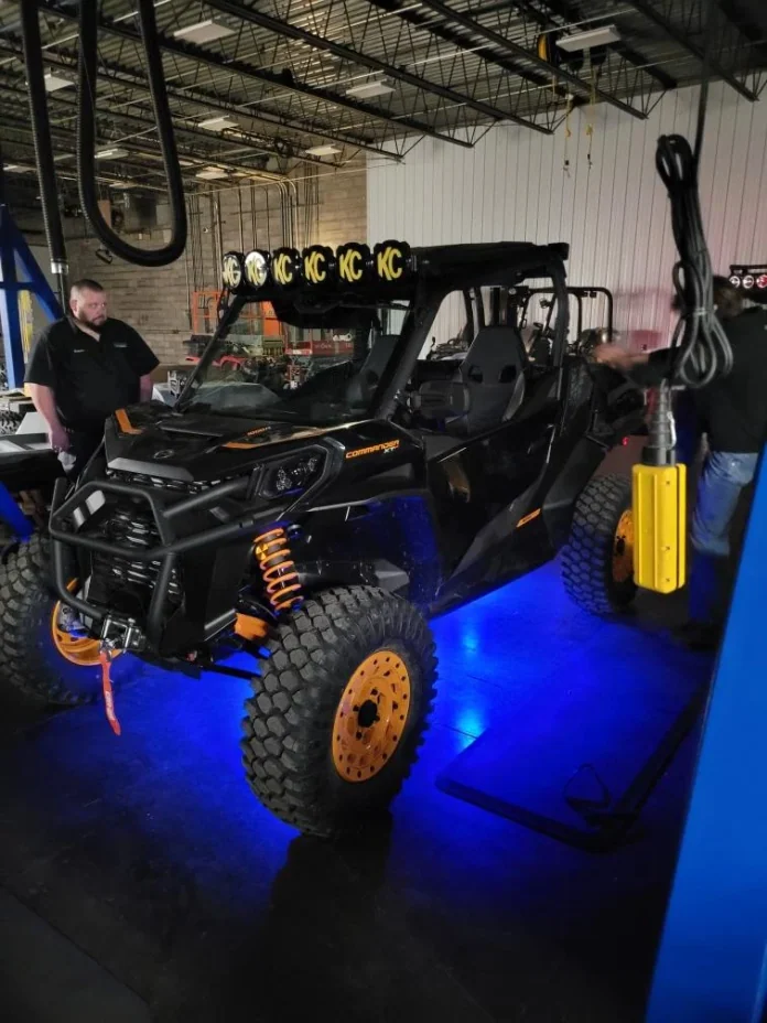
Featured reference photograph: Can Am Commander with KC Rock Lights; archival reference photograph. It illustrates the vehicle family or accessory context, not the exact current trim or an independently tested installation. MonkeyMania747 / Wikimedia Commons / CC BY 4.0. Resized and converted to WebP; photograph remains under its stated license.
Plan UTV electrical accessories by their documented operating conditions and the complete supply path, not by adding light-bar lengths or trusting an outlet’s voltage label. A load worksheet can identify questions before purchase. It cannot approve a fuse, cable, connector or installation by itself.
This guide uses manufacturer lighting data and explicitly labeled arithmetic. It does not give a universal wiring diagram. Vehicle-specific and kit-specific instructions must establish the permitted circuit and protection.
Record the exact electrical data
| Worksheet field | What to enter |
|---|---|
| Accessory | Manufacturer, SKU, quantity and operating modes |
| Published demand | Maximum/design current where supplied, with the stated voltage and conditions |
| Supply path | Approved connector, harness, switch/relay and vehicle supply |
| Shared equipment | Every other accessory on that path, including intermittent loads |
| Unresolved information | Any missing maximum draw, rating or permitted installation detail |
Do not assume a peak output rating for the vehicle is all available for accessories at idle. The original systems also draw power, and the outlet or harness may limit the installation independently of the charging system.
A transparent two-pod example
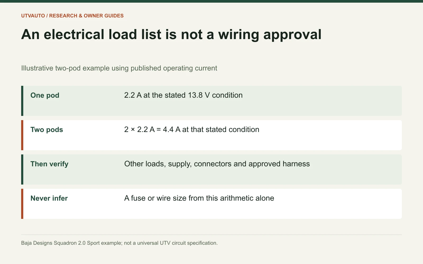
Baja Designs lists Squadron 2.0 Sport demand as 30 W / 2.2 A at 13.8 V per light. At that stated condition, two listed 2.2 A loads total approximately 4.4 A. The result excludes every other connected device and does not automatically describe maximum current under all permitted voltages.
For comparison of arithmetic only, 60 W divided by 13.8 V is about 4.35 A; the slight difference reflects the rounded published labels. Use the manufacturer’s actual design requirement and instructions when choosing an approved installation.
Resolve labels that do not describe an identical condition
The RIGID 910613 product page lists both 84 W and 4.94 A at 14 V. Those are not directly equivalent through simple multiplication: 4.94 × 14 is about 69.2 W. Obtain clarification of maximum/design current rather than silently treating the smaller number as a wiring limit.
Distinguish input electrical power from advertised light output. Raw lumens, beam distance and electrical demand are separate fields. A product comparison that replaces missing current data with a guessed efficiency is not a reliable circuit plan.
Verify every component in the supply path
Confirm the vehicle supply, connection point, harness, connectors, relay/switch and protective device under the actual instructions. A plug that physically mates is not proof of a permitted load. Keep wiring away from hot, sharp and moving components through the specified routing.
The RANGER catalog’s wiring arrangements separates platform and light/switch combinations. Treat that as a reason to identify the full application, not permission to select a different harness merely because it looks similar.
Stop when the installation is not documented
Get qualified support when a required rating is unknown, fuses repeatedly open, a connector gets hot, insulation is damaged or an earlier owner’s wiring cannot be identified. Do not bypass protection or install a larger fuse to stop a recurring fault.
Bring the completed accessory list and the actual kit instructions to the installer. The light-bar buying guide covers beam and package selection, while battery maintenance covers a different question: battery type, charging and storage.
Editorial collection: September 2026. This is a topic collection label, not a backdated first-publication date.